A guide or straightening roller is defined by the material it contacts and the geometry it must control. Groove profile, working diameter, edge radius, runout, surface condition and mounting arrangement should be specified before choosing the internal bearing construction.
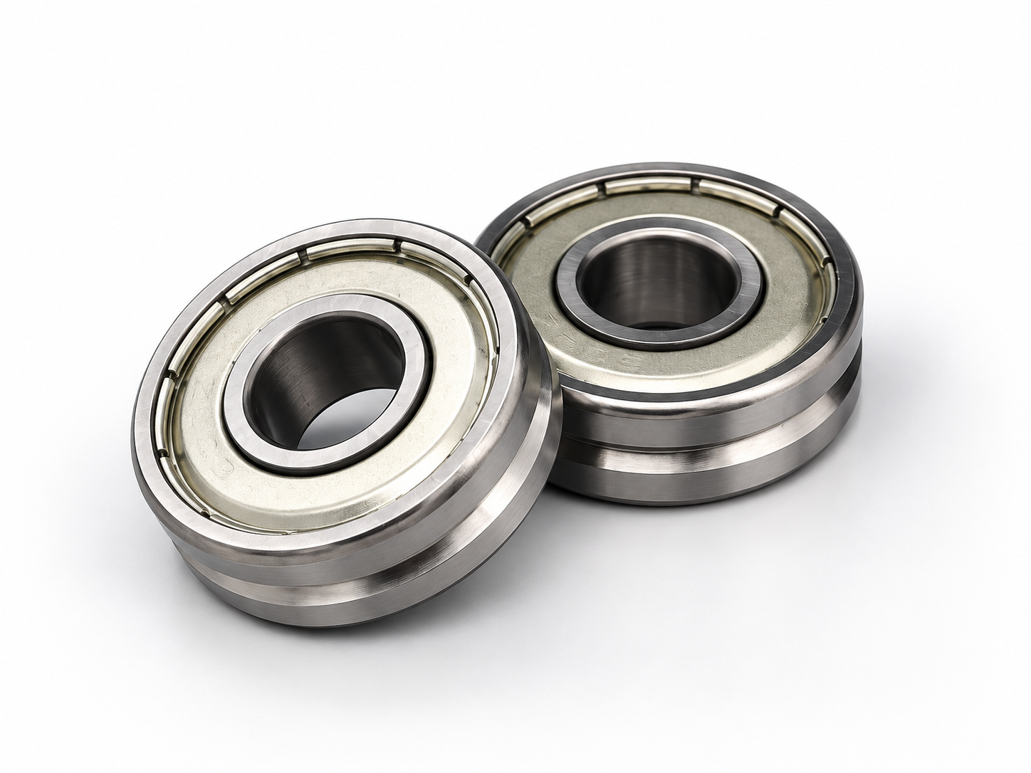
The working profile is the product interface
The current NLHB series map contains two verified product routes: V-groove bearings and U-groove bearings. Their groove geometry guides wire, cord or other moving material in different ways.
Product roles and design boundaries
The verified public range is organised into V-groove and U-groove guide-wheel bearings. The groove is machined directly into the bearing outer ring; therefore, profile geometry and rotational accuracy must be reviewed together.
Material, hardness, coating and surface finish should be selected from contact pressure, wear mode, contamination and the sensitivity of the guided material. Other custom profiles require separate drawing review and are not listed as standard series here.
Series map
V-groove guide-wheel bearings
Single centred V groove machined in the outer ring. Specify groove angle, contact position, working diameter and edge transition.
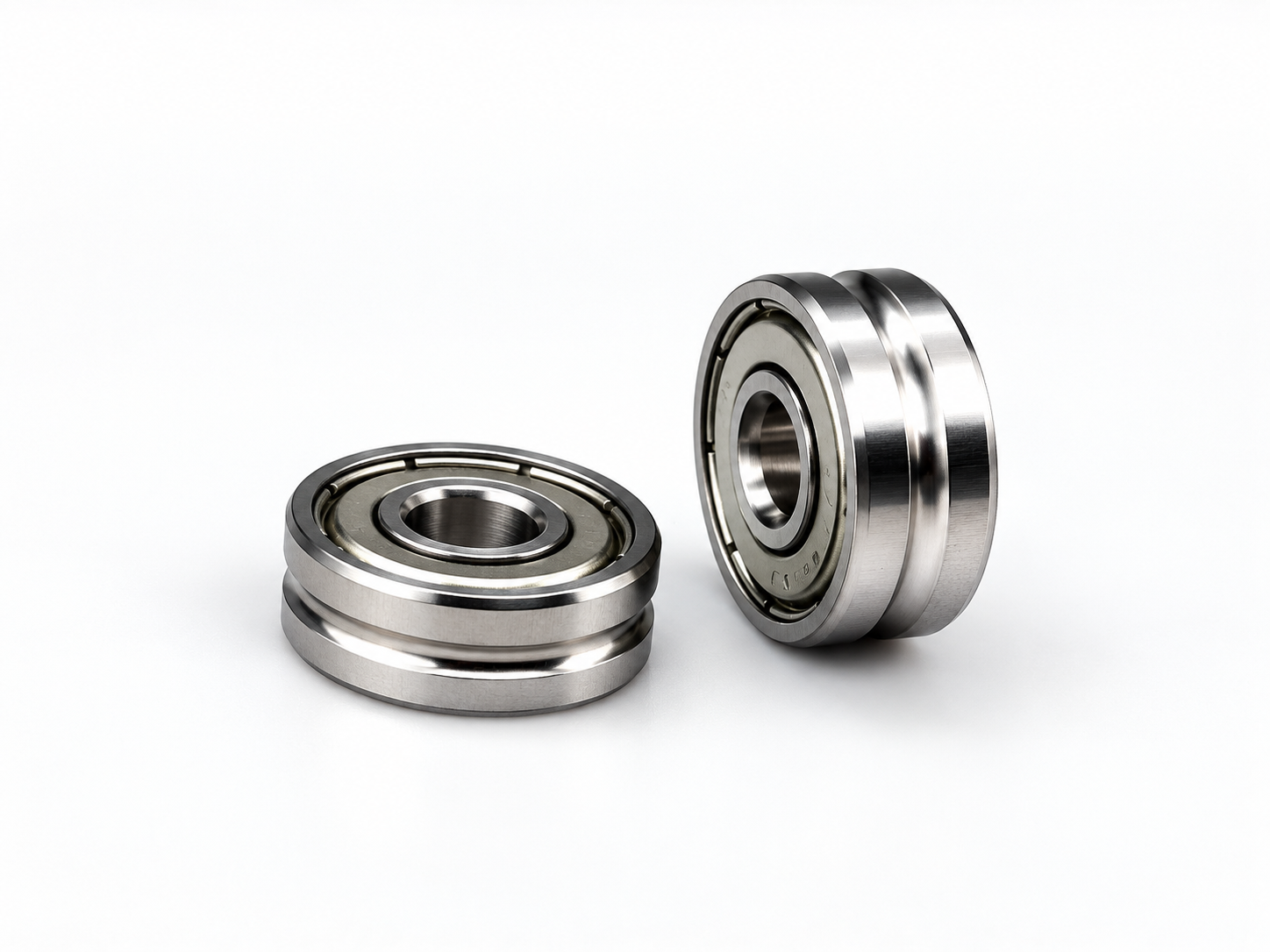
U-groove guide-wheel bearings
Smooth rounded U groove represented by the 624U sample. Specify groove radius, width, depth and supported material diameter.
Selection framework
| Drawing item | Define | Verification focus |
|---|---|---|
| Working profile | V angle, U radius, compound curve, groove width and depth | Profile trace or optical comparison |
| Rotating datum | Bore, shoulder, side face and working diameter | Radial/axial runout to the installation datum |
| Contact material | Diameter, hardness, surface sensitivity and contamination | Finish, edge transition and wear compatibility |
| Operating condition | Speed, load direction, wrap/contact angle and duty cycle | Bearing construction, lubricant, heat and rigidity |
Do not dimension the groove without defining the installation datum
A correct groove shape can still run eccentrically if the profile and runout tolerances are not related to the bore, shaft or mounting shoulder used in the machine.
Minimum drawing and application data
Custom roller development is faster when the first inquiry contains both the part geometry and the material path.
- Section view of the working groove with angle, radius, width, depth and edge transitions.
- Bore, outside diameter, all widths, shoulders, chamfers and mounting method.
- Material being guided or straightened, including section size and surface sensitivity.
- Speed, load direction, duty cycle, impact and environmental contamination.
- Runout, profile, surface finish, hardness/coating and inspection datum requirements.
- Sample quantity, validation method and production documentation requirements.
Profile and runout require separate checks
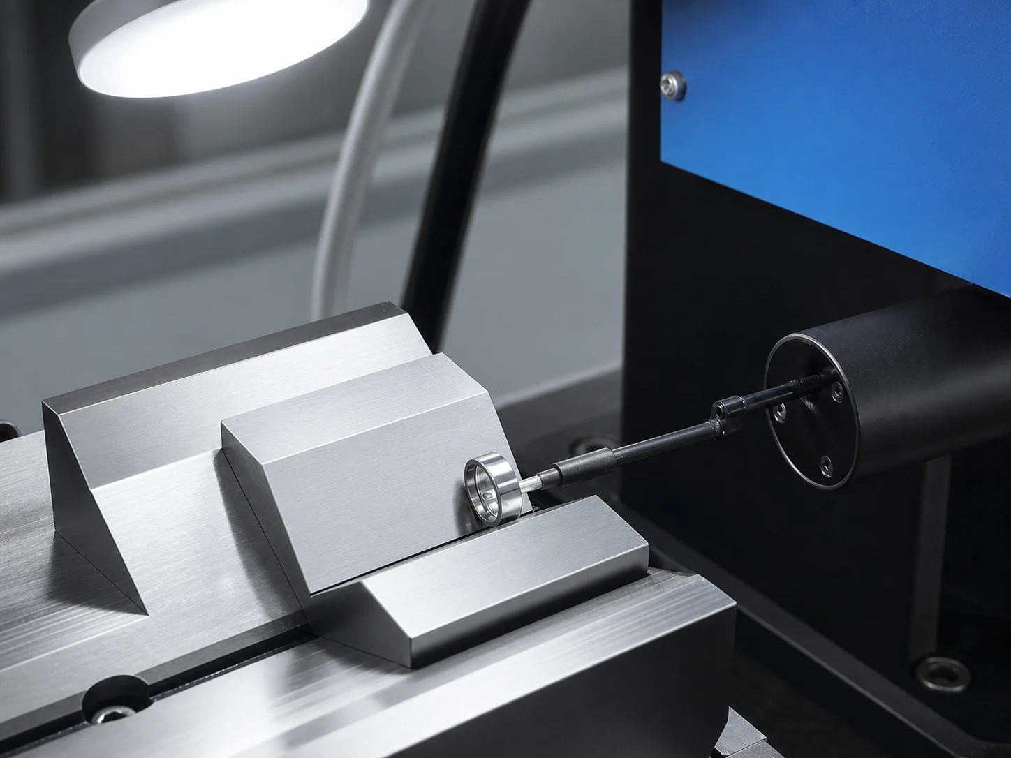
Profile inspection confirms the groove form; runout inspection confirms how that form rotates about the installation datum. Both are required where guidance accuracy depends on the working surface.
Custom quotation checklist
- Section view of the working groove with angle, radius, width, depth and edge transitions.
- Bore, outside diameter, all widths, shoulders, chamfers and mounting method.
- Material being guided or straightened, including section size and surface sensitivity.
- Speed, load direction, duty cycle, impact and environmental contamination.
- Runout, profile, surface finish, hardness/coating and inspection datum requirements.
- Sample quantity, validation method and production documentation requirements.
Frequently Asked Questions
What is the difference between a guide wheel and a straightening roller?
A guide wheel mainly controls the material path; straightening rollers work as a coordinated set to change curvature.
Is groove angle enough to define a V wheel?
No. Include working diameter, groove depth, edge transition, width and the installation datum.
How should a U-groove radius be selected?
It should be evaluated against the material diameter, contact pressure, guidance requirement and surface sensitivity.
Why specify runout separately from profile?
Profile describes shape; runout describes how the shape moves relative to the mounting axis.
Can a worn sample be copied directly?
A worn sample is evidence, not the original geometry. Compare wear patterns with machine interfaces and functional requirements.
What speeds up a custom quotation?
Provide a section drawing, application photos, material path, load/speed data, inspection datums and target quantity.
Related engineering guides
References
Evidence version: guide-series-v1.1 · Checked 2026-09-21. Images are representative. Final dimensions, ratings, inspection limits and supply conditions are confirmed against the requested model, drawing and order.