Copper and aluminium conductors, tinned copper PV ribbon and insulated cable are soft compared with the rollers that guide them. A groove that is slightly too tight, a burr, or a roller that stops turning for a moment can leave a mark that becomes a defect in the finished product. This guide explains how to size the groove, what to agree about roller materials and surfaces, how speed and tension affect bearing choice, and what to include in an enquiry.
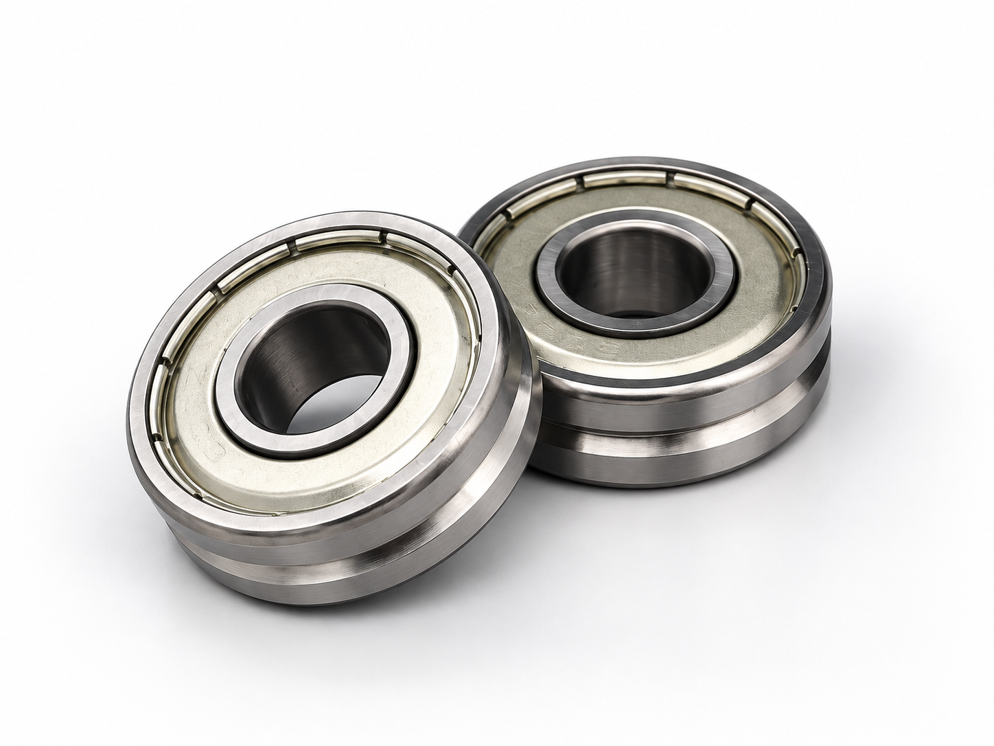
Soft conductors record every defect of the roller
A hard conductor tolerates a roller that drags or has a small burr. Copper wire, PV ribbon and cable jackets do not: the roller must turn freely at line speed and present a smooth groove with no sharp edges.
Where these rollers are used
Copper and aluminium wire drawing
Guide rollers between dies, at the capstan exit, annealer and spooler; high speed, drawing lubricant present.
Cable stranding and extrusion
Guide conductors and cores into the stranding head and extruder, and the finished cable to the take-up.
PV ribbon and flat wire
Guide flat, tin-coated copper ribbon through rolling, annealing, coating and spooling without twisting or scratching the coating.
Why soft conductors get marked
| Mark or defect | Typical roller cause | What to check or specify |
|---|---|---|
| Longitudinal scratch | Burr or rough spot in the groove, or particles embedded in the groove | Groove finish, edge rounding, cleanliness of the groove |
| Flattened or pinched round wire | Groove radius too small or groove too narrow | Groove radius relative to conductor size |
| Periodic mark at fixed spacing | Damage on the groove surface, or roller runout | Groove condition; runout of the groove relative to the bore |
| Scuffing or smearing | Roller stops or slips momentarily and the conductor slides on it | Bearing torque, seal friction, grease type, roller inertia |
| Edge damage on ribbon | Flat groove too narrow, or sharp groove corners | Groove width and corner radius relative to ribbon width |
| Twisted or rolled ribbon | Rollers misaligned, or groove shape does not locate the ribbon | Alignment of consecutive rollers; flat groove with defined side walls |
Groove radius versus conductor size
- Round wire and cable: the groove radius should be slightly larger than the conductor radius so the wire sits in the groove bottom without being pinched. A groove much larger than the wire lets it move sideways and can cause twisting.
- Several sizes on one roller: design the groove for the largest conductor and check that the smallest one is still located. Where the size range is wide, separate rollers per size range are the better solution.
- Flat PV ribbon: use a flat-bottomed groove slightly wider than the ribbon, with rounded corners, so the ribbon edges do not touch a sharp edge.
- Insulated cable: the jacket deforms under pressure, so contact pressure and groove radius together decide whether the jacket is marked.
- Write groove radius, groove width and groove depth on the drawing. The ratio between groove and conductor is decided by the line designer; we machine to the agreed dimensions.
Roller materials and surface options
Roller body material and any surface treatment or coating should be agreed per application and written on the drawing. The options below are the questions to settle; the choice depends on conductor material, lubricant and the defect you need to avoid.
| Question to agree | Options to consider | Trade-off |
|---|---|---|
| Groove hardness | Hardened bearing steel · other steels · non-metallic tyres | Hard grooves resist wear and embedded particles; softer surfaces are gentler but wear faster |
| Corrosion | Bearing steel with protection · stainless steel | Drawing emulsions and humid annealing areas can cause rust on the groove |
| Surface treatment or coating | To be specified by the customer and agreed before quotation | Coatings change friction and wear behaviour; confirm availability and supplier per order |
| Groove finishing | Ground · turned · polished groove | Ground or polished grooves give a smoother surface and more consistent geometry |
Speed, tension and bearing selection
Many wire and cable guide rollers carry very little load but run at high speed. The main bearing risk is not overload but the roller failing to accelerate or to keep turning with the conductor, which causes slipping and marks.
| Operating condition | Bearing consideration |
|---|---|
| High line speed | Deep groove ball bearings with suitable precision and clearance; check the speed limit of the seal type chosen |
| Very low conductor tension | Low starting torque matters: shields, low-friction seals and a light grease fill |
| Frequent start and stop | Keep roller mass low so the roller follows the conductor during acceleration |
| Drawing lubricant or emulsion present | Contact seals or a labyrinth on the roller to keep fluid out of the bearing |
| Higher tension or wrap angle | Check bearing load; consider larger bearings or two bearings with suitable spacing |
Contact seals give better protection but add friction; see sealed bearing speed limits for how seal lip speed limits the permissible speed. For running accuracy, a P6 or P5 deep groove ball bearing combined with a groove finished relative to the bore keeps runout low; see precision grades P4, P5 and P6.
Common mistakes
- Using one groove size for several conductor sizes without checking the smallest and largest.
- Specifying a contact-sealed bearing with a heavy grease fill on a low-tension line, so the roller stalls.
- Leaving groove edges sharp on ribbon rollers.
- Allowing drawing lubricant to reach a shielded bearing with no additional protection.
- Replacing one roller in a line with a different groove size or bearing, which changes the conductor path.
How we make wire and ribbon guide rollers
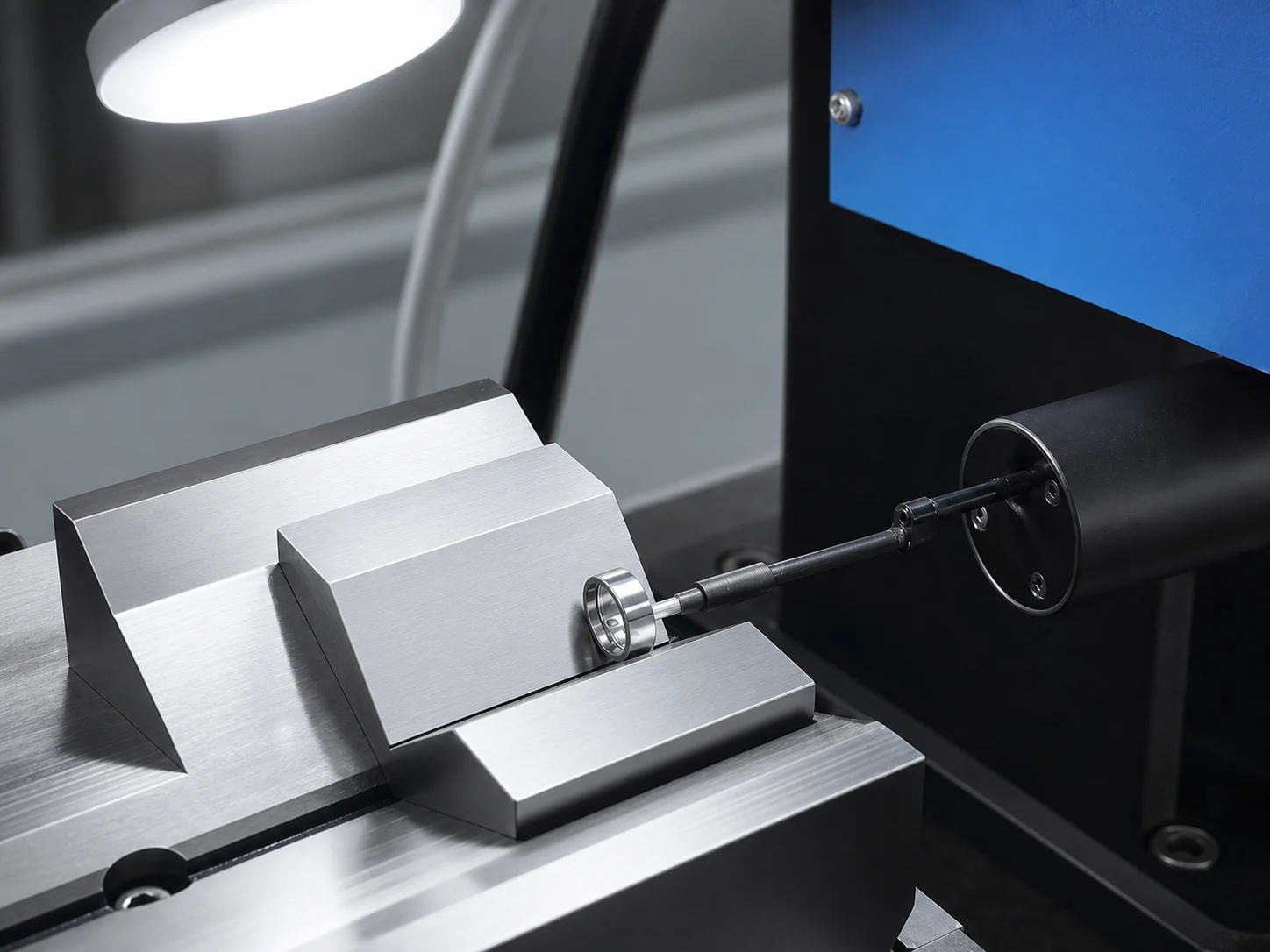
We make U-groove, V-groove and flat-groove guide rollers for cable, wire and PV ribbon lines to sample or drawing. Groove machining, raceway grinding, superfinishing and assembly are done in our Cixi factory; heat treatment is carried out by a long-term partner. Materials, surface treatments and inspection items are confirmed per drawing before quotation. NLHB manufactures miniature and deep groove ball bearings up to P4 precision, and double row angular contact bearings and track rollers up to P6.
Evidence from our workshop

What to send for a quotation
- Drawing or sample of the roller, with groove radius, width and depth.
- Conductor type and size range: round wire, ribbon width and thickness, or cable diameter.
- Line position and maximum line speed.
- Conductor tension and wrap angle, if known.
- Presence of drawing lubricant, emulsion or moisture.
- Required material, surface treatment and groove finish.
- Bearing type, seal and grease, if specified; quantity.
Frequently Asked Questions
Why is our copper wire scratched after a guide roller?
Check the groove for burrs, embedded particles and wear, and check whether the roller turns freely at line speed. A roller that stalls or slips briefly also leaves marks.
How large should the groove radius be compared with the wire?
Slightly larger than the conductor radius, so the wire sits in the groove bottom without being pinched or moving sideways. The exact ratio is agreed on the drawing with the line designer.
What groove shape suits PV ribbon?
A flat-bottomed groove slightly wider than the ribbon, with rounded corners so the ribbon edges do not touch a sharp edge.
Can you supply coated guide rollers?
Surface treatments and coatings are agreed per drawing. Send the requirement and we confirm what can be supplied before quotation.
Should wire guide rollers use sealed or shielded bearings?
Shields give lower torque, which helps on low-tension lines. Contact seals protect better where drawing lubricant or moisture is present. The choice depends on tension, speed and environment.
Related guides
Published 2026-09-25. Images show our own workshop and representative products. Final dimensions, grades, inspection limits and supply conditions are confirmed against the requested model, drawing and order.