On steel cord stranding, calendering and radial tire building lines, guide rollers change the direction of the cord, hold its position across the line and keep tension even between spools and the process. A roller that runs out, marks the brass coating or seizes from dust shows up as broken filaments, uneven cord spacing or line stops. This guide explains what the roller has to do, which geometric properties matter, how to seal the bearing, and what to put on a drawing or RFQ.
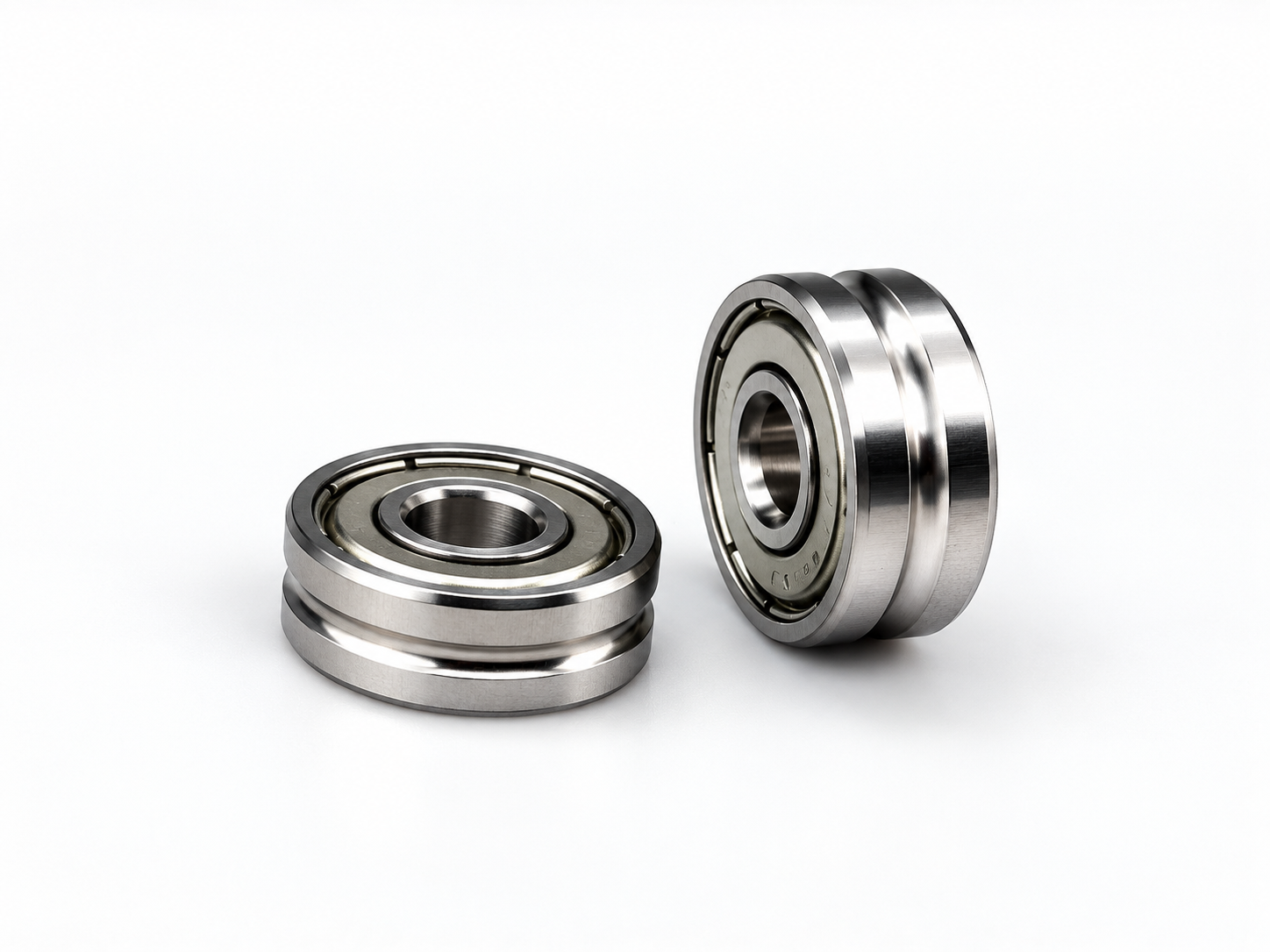
The roller is part of the cord path
Every guide roller the cord passes over adds bending, friction and a chance of surface damage. Groove shape, runout and free rotation decide whether the roller follows the cord smoothly or drags and marks it.
Where guide rollers sit on a steel cord and tire line
Stranding and bunching
Guide filaments and strands between pay-off, twisting and take-up; groove wear here affects lay and filament breakage.
Creel and calender feed
Hold many cords in position and spacing as they enter the calender, where cord spacing becomes the ply specification.
Bead wire and tire building
Guide bead wire and cord plies to the drum; rollers work close to rubber compound and must not seize or leave marks.
For general groove and diameter selection across all wire types, see wire straightening and guide roller selection. This article covers the requirements specific to steel cord and tire lines.
What each roller property does to the cord
| Roller property | Effect on the cord | What to specify |
|---|---|---|
| Groove profile (U, V or flat) | Decides how the cord is supported and whether it can roll or climb the groove wall | Profile type and the cord or strand size it must carry |
| Groove radius | Too small pinches the cord and damages the coating; too large lets the cord wander | Groove radius relative to the cord diameter, per drawing |
| Working diameter | A small diameter bends the cord more sharply at each wrap | Working diameter agreed with the line designer's minimum bending diameter |
| Radial runout of the groove | Produces a periodic tension change once per roller revolution | Runout limit of the groove relative to the bore, per drawing |
| Face runout / groove position | Moves the cord sideways and changes spacing on multi-cord rollers | Groove position tolerance from the reference face |
| Groove surface finish | Rough or scratched grooves abrade the brass coating and pick up rubber | Finish requirement on the groove, measured on the groove itself |
| Rotational torque | A stiff roller drags the cord, raises tension and wears the groove | Seal type and grease chosen for low starting torque |
Groove geometry and runout
The groove must support the cord over an arc without pinching it. Groove radius, groove depth and the angle of the side walls should be dimensioned on the drawing together with the cord size range the roller must handle. Where one roller carries several cord sizes, the groove is designed for the largest size and checked for lateral stability with the smallest.
Runout of the groove is the property most often left off drawings. Because the cord follows the groove bottom, groove runout relative to the bore translates directly into a tension fluctuation. The runout of the roller is the sum of the bearing's own radial runout and the machining of the groove relative to the bearing seat. The practical way to control it is to finish the groove after the bearing is fitted, or to grind the groove with the outer ring located on the bearing raceway, and to state the limit as groove runout relative to the bore.
Groove surface finish
- Steel cord is usually brass-coated for rubber adhesion. A groove that scratches the coating reduces adhesion in that area, so the groove finish matters as much as its geometry.
- Specify the finish on the groove surface itself, not on the outer diameter. The groove radius is harder to finish than a cylindrical surface.
- A hardened, ground groove holds its finish longer than a soft or turned groove. Hardness and whether the groove is ground or turned should be agreed on the drawing.
- Worn grooves develop a track that matches the cord. When the cord size changes, a worn track can pinch or mark the new cord even if the roller still turns freely.
Sealing against rubber and steel dust
| Seal option | Advantage | Limitation |
|---|---|---|
| Metal shield (ZZ) | Low friction, low starting torque | Non-contact; fine steel dust and rubber particles can enter over time |
| Contact rubber seal (2RS) | Better exclusion of dust and mist | Higher friction than a shield; the seal lip adds torque |
| Shield or seal plus labyrinth or cover on the roller | Keeps particles away from the seal | Needs space in the roller design and must be agreed on the drawing |
On tire lines, the choice is a balance between exclusion and torque. A lightly loaded cord guide roller that drags causes more damage than one that runs a little shorter between changes. Where dust is heavy, a contact seal with a low-torque grease is usually the starting point; where the roller must turn with very low cord tension, a shielded bearing behind a labyrinth on the roller body may suit better. The grease type and fill should be chosen for the line temperature and stated on the order.
Maintenance intervals as a principle
Replacement intervals depend on line speed, cord type, dust level and how many cord sizes pass through the same roller, so there is no single figure that applies to every line. A workable approach is to set the interval from your own records:
- Record the installation date and position of each roller.
- At planned stops, check free rotation by hand, noise, axial play and the groove surface under light and magnification.
- Replace rollers on a condition basis at first, and note the running time at which each position needed replacement.
- Use that history to set a fixed interval per position, shorter for positions with heavy dust or high wrap angle.
- Replace rollers on the same multi-cord shaft together, so groove diameters stay matched.
Common failure causes
- Groove track worn into the surface after long running on one cord size.
- Bearing seized or stiff from rubber particles or steel fines that entered past a non-contact shield.
- Periodic tension variation from groove runout that was not specified on the drawing.
- Coating damage from a groove radius that is too small for the cord.
- Uneven wear across a multi-cord roller because of misalignment between rollers.
How we make cord guide rollers
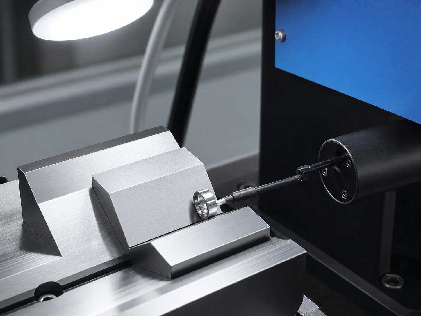
Groove turning, raceway grinding, superfinishing and assembly are done in our Cixi factory; heat treatment is carried out by a long-term partner. We check roundness, raceway profile and surface finish on our own instruments, and we make U-groove, V-groove and flat guide rollers to sample or drawing. NLHB manufactures miniature and deep groove ball bearings up to P4 precision, and double row angular contact bearings and track rollers up to P6.
Evidence from our workshop

What to send for a quotation
- Drawing or sample of the roller, with groove profile, groove radius and working diameter.
- Cord or strand size range the roller must carry.
- Line position: stranding, creel, calender or tire building.
- Required groove runout and groove surface finish, if specified.
- Seal type, grease and working temperature.
- Line speed and approximate cord tension.
- Quantity per order and per year.
Frequently Asked Questions
Why does cord break or lose coating at one guide roller?
Common causes are a groove radius too small for the cord, a worn groove track, a rough groove surface, or a bearing that has become stiff and drags the cord. Check the groove under magnification and the roller's free rotation first.
Should a steel cord guide roller use ZZ or 2RS bearings?
A contact seal (2RS) excludes rubber and steel dust better but adds friction. A shield (ZZ) runs with lower torque but lets fine dust in over time. The choice depends on dust level and how freely the roller must turn.
Why specify groove runout rather than bearing runout?
The cord runs on the groove bottom, so the runout that affects tension is the groove relative to the bore. It includes both the bearing's runout and the machining of the groove.
How often should cord guide rollers be replaced?
There is no universal interval. Start with condition-based replacement, record running time per position, and set fixed intervals from that history.
Can NLHB make guide rollers to our existing sample?
Yes. We make U-groove, V-groove and flat guide rollers to sample or drawing, and confirm groove geometry, seal type and inspection items before quotation.
Related guides
Published 2026-09-25. Images show our own workshop and representative products. Final dimensions, grades, inspection limits and supply conditions are confirmed against the requested model, drawing and order.